Your location: Home > ACCESSORIES > WIRING HARNESSES > MULTI-FUNCTION WIRING HARNESSES (FOR STREET LEGAL LIGHT BARS)
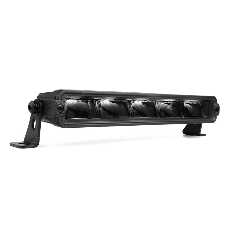
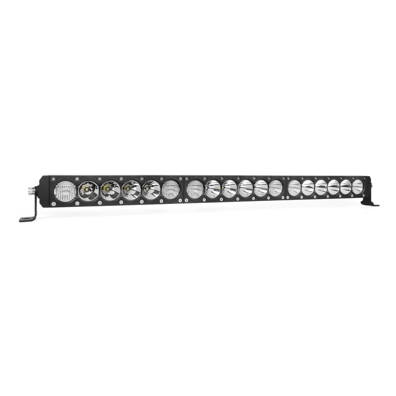
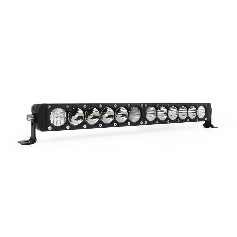
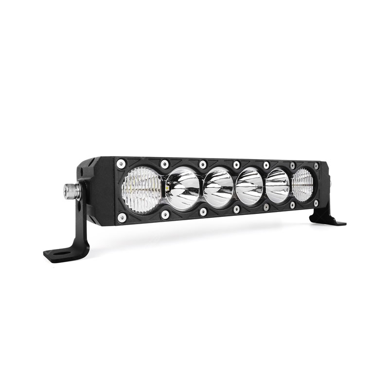
This is a general installation guide on how to wire up a piece of multi-function C6F or C6H wiring harness and a switch panel onto the LED light. Theoretically, these instructions can apply to any car, we will be using OGA street legal 46 series 20 inches combo LED light bar as a reference light to show you how to wire an LED light bar with a multi-function C6H wiring harness and switches panel.
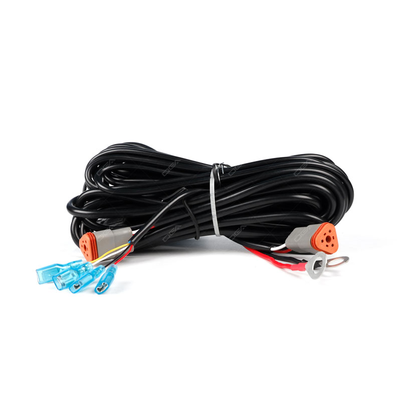
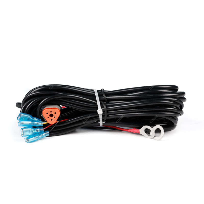
Before we get started, take a good look at the LED light bar wiring harness kit on how to wire up them to the switches panel. You will notice that this wiring harness kit and the switch panel are specially made for the OGA 46 series street legal LED light bars. Without further ado, let us jump right into it.
Step 1: Plan the wiring from the engine bay into the car interior, find an appropriate spot for the switches panel to be mounted. If necessary, drill four holes and use screws to mount the switch panel. Also, find the best mounting locations for the LED light bar and the controller box from the wiring harness. And then we finish the wire routing first.
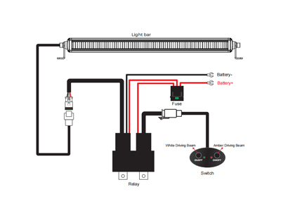
Step 2: Connect the wiring harness with the on-off rocker switches panel.
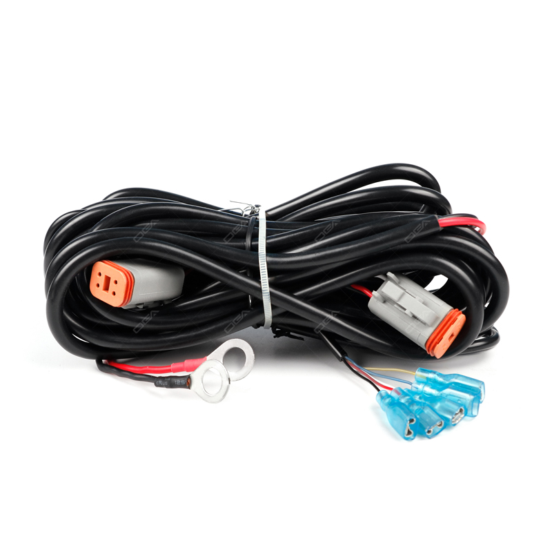
There will be five wires coming out from the wiring harness kit, for the LED lights to achieve independently functional beam patterns, you have to make sure these five wires are connected correctly with the rocker switches panel.
- Red wire is to be connected with the positive wire.
- Black wire is to be connected with the negative wire.
- White wire is to be connected with the on-off rocker switch to control the high beam (auxiliary driving beam).
- Blue wire is to be connected with the on-off rocker switch to control the auxiliary fog beam.
- Yellow wire is to be connected with the on-off rocker switch to control the strobe light.
Note: At the end of each wire, there is a connector that has a small spot. You have to press that small spot for the connector to come off from the rocker switch panel. It is suggested that you leave the surface that has the spot toward the outside if you needed to disconnect the switches panel from the wiring harness kit afterward.
There are two LED indicators on each rocker switch, if the bottom one is on, it means you had correctly connected the wiring harness with the on-off rocker switches panel. And when the top one is on, it means the specific beam pattern is functioning, and so, you can actually decide which rocker switch for which beam pattern by switching the wires connected to the rocker switches.
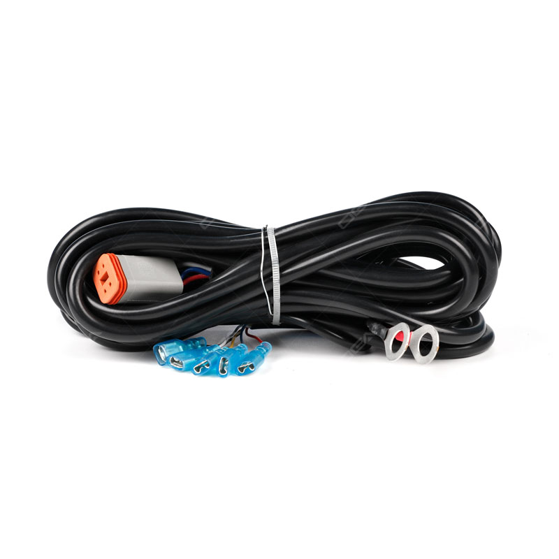
Step 3: All you need to do is simply find the female DT connector from the wiring harness kit and then connect it to the male DT connectors from the LED light bars.
Step 4: Connect the red (+) wire to the positive battery terminal from the vehicle. Connect the black (-) wire to the negative terminal on the battery.
Step 5: Turn on the LED light bar by using the switch panel and verify if each beam pattern turns on and off properly. Finally, you can enjoy switching the different beam patterns from your new wired and mounted SAE approved LED light bar. More

TO BE SEEN ONE SECOND AHEAD


 2026-06-10