In modern US and EU vehicles, the high beam trigger signal is typically sent from the high beam switch to the Body Control Module (BCM) or Lighting Control Module (LCM), which manages the vehicle's lighting system. The signal is then distributed via CAN bus or PWM voltage signals to control the lights. Therefore, to trigger auxiliary LED lights using the high beam switch, the trigger signal needs to be appropriately accessed and fed into a relay circuit.
1. Locating the High Beam Trigger Signal
The high beam trigger signal generally comes from the high beam switch (typically located on the stalk of the steering wheel), which sends the signal to the BCM or LCM. In US and EU vehicles, this trigger signal often comes in the form of PWM voltage. Here are some common locations:
High Beam Switch Signal Line: You can confirm this signal line by checking the vehicle's electrical wiring diagrams or using a multimeter.
BCM or LCM: These modules control the high beam signal distribution, and in some vehicles, the signal may be passed via CAN bus.
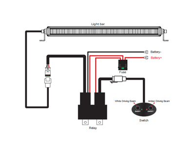
2. Connecting the Signal to the Relay
To connect the high beam signal to the relay, follow these steps:
Find the High Beam Signal Line: Identify the high beam signal line coming from the high beam switch or LCM using a multimeter.
Connect to the Relay Trigger: Attach the high beam signal line to the control pin (input) of the relay. This allows the relay to be triggered when the high beam is activated.
Connect the Relay Output to the LED Light Power: The relay's output pin (control pin) connects to the auxiliary LED light power line. When the power rating of the relay is too high for direct connection, it may cause current overload. In such cases, a low-current relay can be used to control the larger relay.
3. Power Connection
Power the LED Lights: The auxiliary LED lights should be powered directly from the vehicle battery to ensure enough current for high-power LED light bars.
Power the Relay Control Board: If you use a control relay board (e.g., Fuse Tap), ensure the power required by the control relay board is minimal to avoid triggering fault codes or electrical load problems.
Fuse Protection: It's recommended to add a fuse with the correct current rating to protect the relay and the power lines.
4. Installation Considerations
Grounding: Make sure all ground lines are properly connected to the vehicle's negative terminal.
Secure Wiring: Ensure that all wiring is tightly secured and insulated to avoid short circuits and poor connections.
Adjust Light Beam Angles: After installation, adjust the auxiliary lights' beam angles to prevent dazzling oncoming drivers.
Testing and Debugging: Test the setup by activating the high beams to ensure the relay works properly and the auxiliary lights illuminate as expected.
5. Possible Challenges
Current Load Issues: Since the high beam circuit might not support large power loads, a relay is necessary to distribute the power properly.
CAN Bus Interference: If the vehicle uses a CAN bus system, you might need a CAN decoder to ensure the signal is properly triggered.
Wrap-up
The high beam trigger signal is used to control the auxiliary lights through the high beam switch, which sends a low-power signal to the relay. The relay amplifies this signal to drive the auxiliary lights, especially high-power LED light bars. Using a low-current relay board for signal triggering and a high-current relay for actual light operation ensures proper functionality and safety in the electrical system. Proper grounding, wiring, and light adjustment are critical to ensure that the system works reliably and legally.
If you want more information about LED lights and better performing automotive lighting products, visit our website www.ogaled.com.


 2026-06-12