What "dim / flicker" usually means
Most auxiliary light problems in the field are not "the lamp is weak," but the lamp is not receiving stable voltage under load. A circuit can look perfect with no load, yet fail the moment current flows—because resistance at a terminal, fuse holder, relay contact, connector pin, or ground point only becomes obvious when the circuit is working.
The single most important rule is simple: measure with the auxiliary lights ON. Continuity checks can pass while voltage drop under load is still excessive.
Set the right test conditions (avoid false conclusions)
Do the diagnosis under the same conditions where the problem happens. Keep the aux lights ON during testing, and if possible run the engine at idle so system voltage is closer to real operation. If the complaint happens only when other accessories are on, recreate it—turn on headlamps, blower, rear defogger, or other loads that make the wiring work harder.
Keep your harness protection in place. If your circuit uses a fuse and relay, leave them in the circuit while testing. The goal is to find the weak point, not bypass safety devices.
The 10-minute voltage-drop routine (4 readings)
This method uses four readings to quickly tell you whether the loss is on the positive side, the ground side, or both. All readings are taken with the aux lights ON.
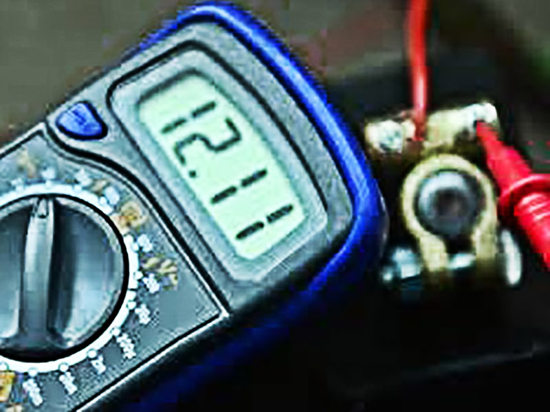
1) Battery baseline (V_batt): Measure Battery (+) → Battery (–). This is your reference system voltage at that moment.
2) Lamp voltage (V_lamp): Measure Lamp (+) → Lamp (–). This is what the light actually receives. If V_lamp is noticeably lower than V_batt, the missing voltage is being lost somewhere in wiring, connectors, relay, fuse holder, or ground.
3) Positive-path drop (V_drop+): Measure Battery (+) → Lamp (+). A high number here means you're losing voltage on the positive delivery path—battery clamp, fuse holder, relay contact, connector, wire, or a poor crimp.
4) Ground-path drop (V_drop–): Measure Lamp (–) → Battery (–). A high number here means the problem is on the return/ground path—paint or rust under a ground lug, a loose bolt, corrosion, or a long/thin ground wire.
How to interpret quickly: High V_drop+ → fix the positive path first. High V_drop– → fix the ground first. Both high → issues on both sides.
How to pinpoint the exact bad spot (scan along the path)
Once you know whether the main loss is on the positive side or the ground side, isolate it by "scanning" along that same path in small steps and watching where the reading changes sharply.
For the positive path, move your measurement point progressively forward: battery clamp → fuse input → fuse output → relay input → relay output → connector → lamp (+). For the ground path, move progressively backward: lamp (–) → ground lug → chassis metal → battery (–).
The location where the voltage drop jumps is where resistance is concentrated.
The most common causes (and what to do)
Fuse holder / terminals overheating: A slightly loose or oxidized fuse contact increases resistance, which creates heat, which worsens contact—then brightness drops or flicker starts. If a fuse holder feels hot, looks discolored, or the plastic is soft, replace it and ensure the terminals grip firmly.
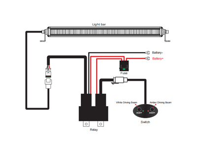
Relay issues (contacts or wiring): A relay can click and still drop voltage badly if contacts are weak or the wiring is wrong. Verify the common mapping: 30 = power in, 87 = power out, 85/86 = coil. Replace questionable relays rather than guessing.
Poor ground (tight but not conductive): A ground bolt can be mechanically tight but electrically poor if the lug sits on paint, rust, or dirty metal. Scrape to bare metal, use a star washer if available, tighten properly, then protect against corrosion.
Long runs (especially roof light bars): Long wire runs magnify every small resistance. If roof lights are dimmer than bumper pods, shorten the high-current path where possible, reduce connector count, and use appropriately sized wiring for the distance and current.
Corroded connectors / water ingress: Intermittent flicker that worsens in wet conditions often points to connector corrosion or pin fit issues. Clean or replace pins and improve sealing and strain relief to prevent micro-movement.
Daisy-chaining multiple lights: Feeding one lamp through another stacks voltage drop and creates uneven brightness. Use proper parallel distribution so each light has a solid feed and return.
A quick example to make it intuitive
If you run two 60 W auxiliary lights, that's about 120 W total. Near charging voltage (around 13.5 V), current is roughly 120 W / 13.5 V ≈ 8.9 A. If the battery is at 13.8 V but the lamp only sees 12.3 V, you're losing 1.5 V in the circuit—often enough to cause obvious dimming, and in some cases driver instability.
Field checklist (for installers and distributors)
- Record V_batt and V_lamp with the aux lights ON (engine idling if possible).
- If dim/flicker occurs, record V_drop+ and V_drop–.
- Scan along the problem side (positive or ground) until you find where the drop jumps.
- Fix the resistance source (terminal, holder, relay, connector, ground)—don't bypass fuses/relays to "make it work."
- Retest and confirm the lamp voltage is close to battery voltage under load.
Bottom line
To wrap up, if you standardize this four-reading voltage-drop routine, most "ystery flicker" cases become a fast, repeatable diagnosis instead of parts-swapping guesswork. For workshops and distributors, consistent wiring practices—and matched harness/relay/fuse solutions—make installations more reliable and reduce returns.


 2026-06-12