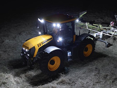
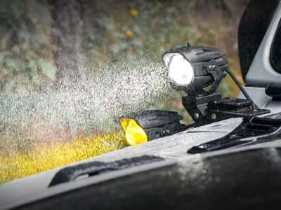
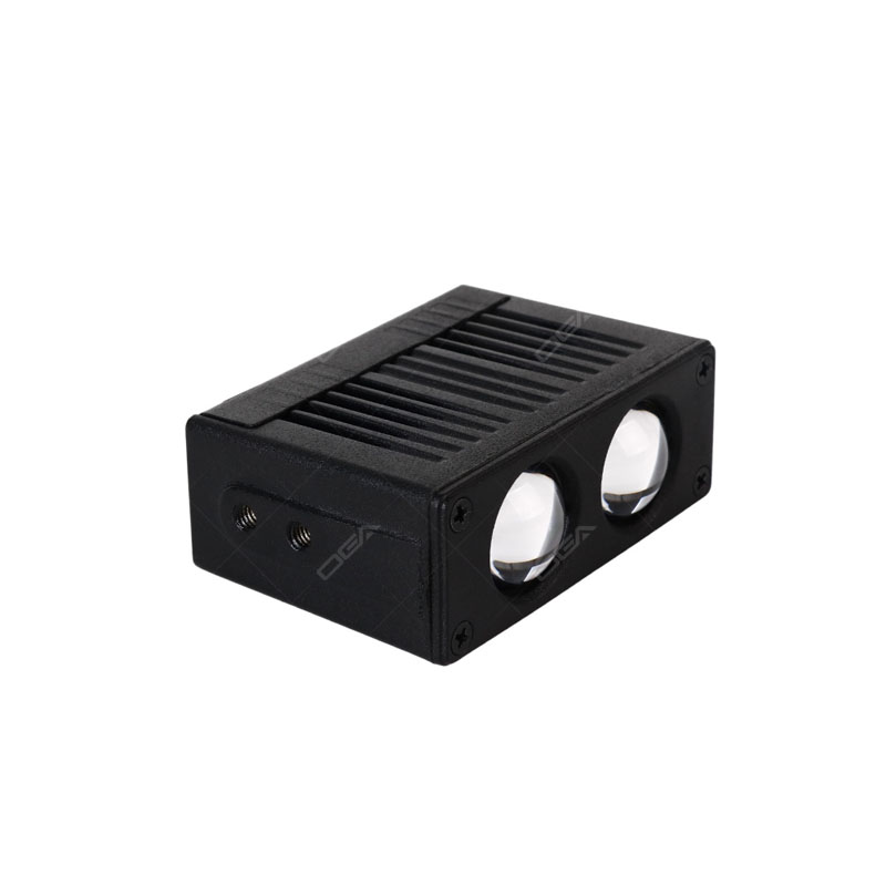
Many people judge an auto light in automotive lighting by what they can see first: beam pattern, brightness, and looks. But in real duty cycles (vibration, stone impact, mud, salt spray, UV exposure, temperature cycling, and long runtimes), the housing system often decides whether the light stays reliable. The housing is not only a protective shell. It is also the mechanical frame, the sealing reference, and in the LED era, part of the thermal pathway that keeps LEDs and electronics alive.
To understand why modern LED work lights are so often built around aluminum housings, it helps to start with the earlier halogen/incandescent era. Back then, housings were mainly designed to mount and protect the headlight bulb. Once LEDs became mainstream, the housing had to help remove heat and keep sealing geometry stable for years. That is why materials and forming processes changed, and why die-cast aluminum alloys such as ADC12 became closely tied to modern aux light housing design.
1) Earlier work lights: halogen/incandescent dominated, and housings were mostly "protective containers"
Before LEDs became mainstream, work lights for vehicles and equipment commonly used incandescent or halogen sources, including sealed-beam style lamps (lens and reflector sealed as one unit). In those products, the housing's role was mainly protection and mounting: it held the lamp, resisted corrosion, and survived vibration and impacts.
1.1 The mainstream legacy route: sheet-metal forming + joining + coating
Steel sheet housings were common because steel is strong, low cost, and easy to mass-produce with simple shapes. A typical process chain looked like this:
1) Sheet-metal stamping (forming sheet steel into shape using a press and die; fast and ideal for mass production) / deep drawing into a cup-like shell
2) Piercing, trimming, and flanging (piercing = punching mounting/cable holes; trimming = cutting the edge clean; flanging = bending the edge to create a stronger lip or an assembly edge)
3) Riveting (joining parts using rivets, including blind rivets; good for thin sheet parts and avoids high welding heat) or welding for brackets and reinforcements
4) Painting/baking enamel/porcelain enamel (painting = spray coating; baking enamel = cured by oven heat for better durability; porcelain enamel = glass-like coating fused at high temperature for corrosion resistance, more traditional)
This approach worked well in the halogen era because the housing mainly provided structure and protection. It did not need complex heat-sink geometry.
Bridge to the next section: once the light source shifted to LEDs, "just strong and corrosion-resistant" was no longer enough. Heat management became a lifetime driver, and the housing was forced to take on a thermal job, which is the real reason the industry's housing strategy had to evolve.
2) Why the LED era forced housing processes to change
LED work lights are popular because they can be efficient and long-lasting. But those benefits depend on keeping temperature under control. If temperatures rise too high, output drops and lifetime shortens.
Bridge to the next section: this is why modern LED work lights treat the housing as more than a shell. The housing becomes a thermal and sealing platform, which changes the "best" material and the "best" manufacturing method.
2.1 The housing becomes a heat platform and a sealing reference (not just a cover)
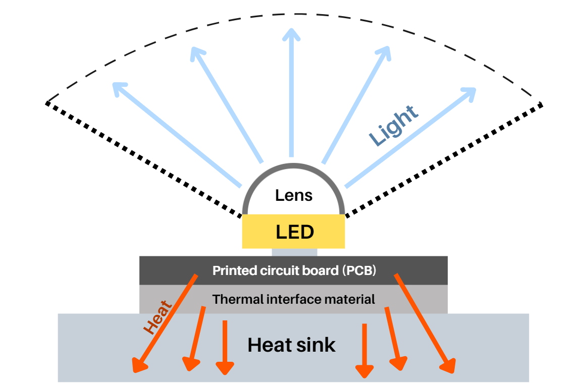
You can picture LED heat flow as a chain:
LED junction (the PN-junction region inside the LED chip; typically the hottest point and the one that most strongly affects lifetime) → PCB (printed circuit board; used to mount and connect components; LED work lights often use metal-core PCBs for better heat spreading) → thermal interface (the heat-transfer layer between two contacting parts, such as thermal grease, thermal pads, or thermal adhesive) → housing/heatsink → ambient air
That shift creates three direct housing requirements:
(1) The housing needs more conductive cross-section and more fin surface area (conductive cross-section = the effective thickness/area that carries heat through the metal; fin surface area = the area exposed to air for convection, larger area usually helps cooling)
(2) The housing needs more stable geometry and assembly consistency (critical dimensions, flatness, and hole positions must be more consistent; gasket compression must be more repeatable so the light stays sealed and doesn't loosen over time)
(3) The structure must keep thermal contact and fasteners stable under vibration (to avoid loosening, leakage, and hot-spot failures).
2.2 Why stamped-steel housings became less attractive for high-power LEDs
Stamping excels at thin shells, but modern LED housings often need thicker heat paths, fin arrays, and integrated features. With stamped steel, achieving those functions typically increases part count and assembly steps. More joints mean more potential leak paths, and more processes make consistency harder. Using thicker steel also increases weight and cost.
As soon as the housing must act like a heatsink and sealing platform, aluminum becomes the natural center of modern aux light design. That leads us to today's mainstream housing materials.
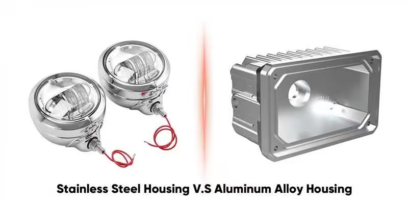
3) Main housing materials today: why aluminum alloys dominate
Modern aux light housings are commonly made from:
– Aluminum alloys (dominant)
– Engineered plastics/composites (engineered plastics = higher-performance plastics such as PA or PBT; composites = plastics reinforced with glass fiber or mineral fillers, often marked as "GF" ; they can be light and corrosion-resistant but usually conduct heat poorly)
– Steel (still used in legacy or cost-driven segments)
Aluminum alloys dominate because they offer a strong overall balance: they conduct heat well enough to serve as a thermal platform, they have adequate strength and stiffness at lower weight, and they work well with durable finishing systems. They also allow integrated features (fins, bosses, sealing grooves) when paired with casting or extrusion.
To understand why certain aluminum alloys are chosen for certain housings, we need a simple definition of aluminum alloys and their major categories.
4) What is an aluminum alloy? The key categories that matter for housings
An aluminum alloy is aluminum with controlled additions of elements (often Si, Mg, Cu, Zn, Mn, Fe) to tune properties such as strength, corrosion behavior, machinability, and most importantly for housings, castability or extrudability.
For aux light housings, the most practical split is by forming route:
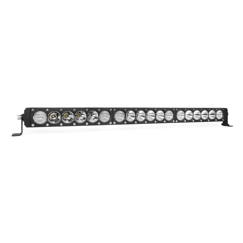
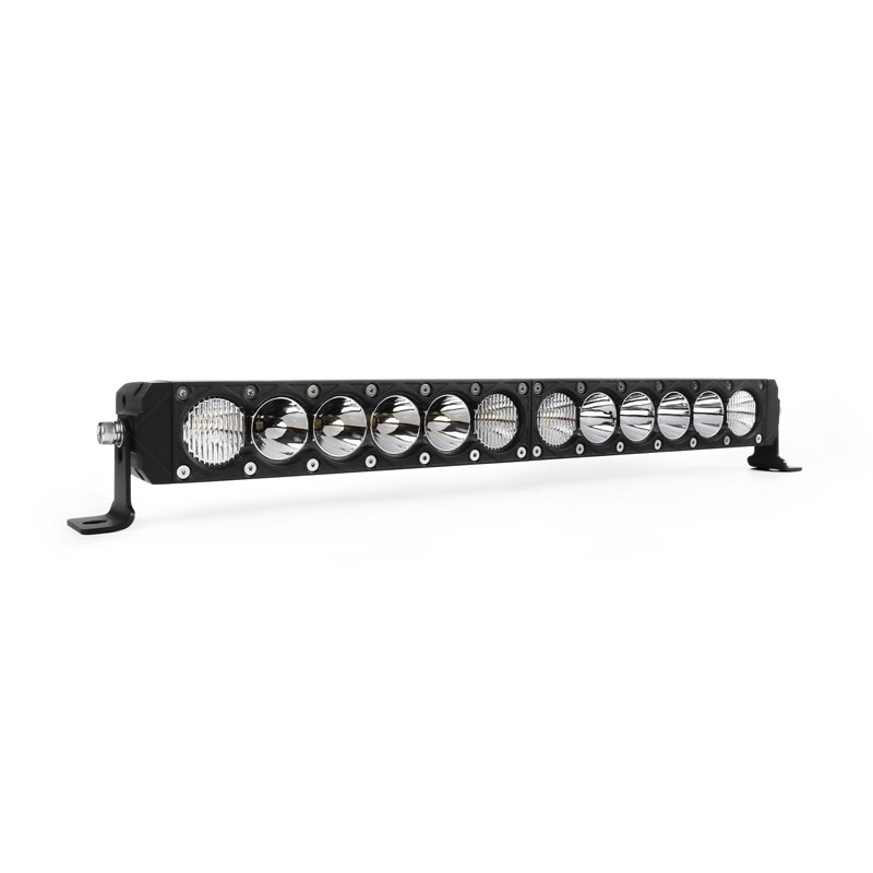
(1) Wrought aluminum alloys (designed for rolling/extrusion/forging): rolling/extrusion/forging (rolling = pressing metal into sheet; extrusion = pushing aluminum through a die to create a constant cross-section profile; forging = shaping with compressive force, often giving higher strength). These are common for long light-bar bodies because the cross-section repeats.
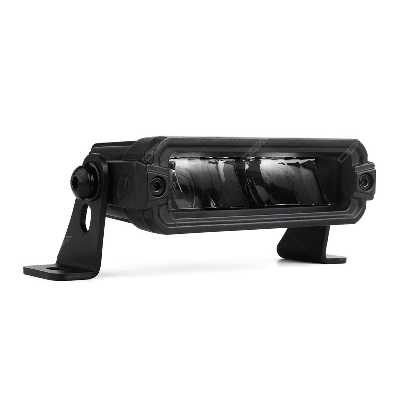
(2) Cast/die-casting aluminum alloys (designed to fill molds): these are used for compact housings with complex 3D geometry.
With that 'wrought vs cast' idea in mind, ADC12 becomes easier to explain. It is a die-casting alloy family designation, and its chemistry is optimized for die casting complex, thin-wall parts.
5) ADC12: where the name comes from, what it means, and why it's used
ADC12 is widely recognized as a Japanese designation under the JIS standards system. In industry communication, "ADC" is the symbol family used for aluminum die-casting alloys, and "12" is the grade number within that family.
Some sources further interpret ADC as "Aluminum Die Casting," or break it down as "A = Aluminum" and "DC = Die Casting." The most careful, standard-aligned way to phrase it is: ADC indicates the JIS die-casting alloy series, and 12 indicates the specific grade (which corresponds to a defined composition range).
In practical engineering terms, ADC12 is often described as an Al-Si-Cu die-casting alloy. Silicon supports fluidity and mold filling (useful for thin walls, fins, sealing grooves, and complex ribs), and copper contributes to higher strength, helpful in vibration-heavy aux light applications.
Extra note: what "ribs" mean in a housing
Ribs (stiffening ribs) are raised strip-like features molded or cast into a housing. They increase stiffness with less material, reduce deformation, and provide structural support for fins and bosses. In thermal designs, ribs can also help spread heat more evenly through the housing body.
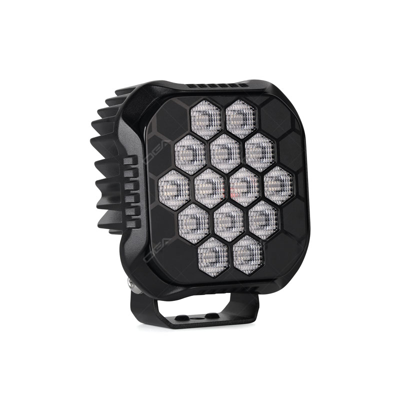
6) How aux light housings are manufactured today
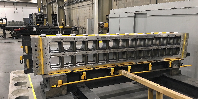
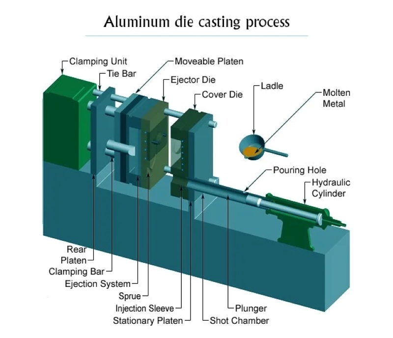
(1) High-pressure die casting (HPDC): For compact LED work lights and aux lights, high-pressure die casting (HPDC) is widely used because it can create fins, ribs, bosses, and gasket grooves in one part with strong repeatability. Below is a more complete end-to-end process flow, including what typically happens before and after the actual casting shot.
1 Design & Die Preparation (Upstream)
The process starts with part engineering: the housing is designed around thermal paths (thick heat cross-sections, fin geometry), sealing geometry (flat gasket lands, groove profiles), and assembly features (bosses, cable exits, mounting points). A die is then designed with gates, runners, overflows, and vents so molten aluminum can fill thin-wall areas quickly while pushing air toward venting locations. Many housings also include draft angles for ejection, controlled wall thickness to reduce shrink risk, and local reinforcements around fasteners.
2 Alloy Melting & Melt Quality Control
Aluminum alloy ingots (commonly ADC12 for die casting) are melted in a furnace and held within a controlled temperature window. Melt quality is managed by removing dross, controlling oxidation, and often performing degassing (to reduce dissolved hydrogen that can contribute to porosity). If required, the melt is filtered or refined to help reduce inclusions. A stable, clean melt is critical for sealing surfaces and consistent machining results.
3 Die Heating, Lubrication & Machine Setup
Before production shots, the die is preheated and maintained at a controlled temperature to stabilize fill behavior and minimize defects. The die cavity is sprayed with a release/lubricant to assist ejection and protect die surfaces. The die casting machine is set for shot parameters such as slow-shot speed, fast-shot speed, intensification pressure, and timing. Proper setup is especially important for housings with fine fins and sealing grooves.
4 Dosing & The Shot (Filling Under High Pressure)
A measured amount of molten aluminum is dosed into the shot sleeve. The plunger then advances in two main phases: a slow-shot phase that moves metal forward while limiting turbulence, followed by a fast-shot phase that rapidly fills the die cavity before the metal begins to freeze. Many production lines use vacuum assistance (or optimized venting) to reduce trapped air, which improves sealing reliability and reduces leak risk.
5 Intensification, Solidification & Cooling
Once the cavity is filled, the machine applies intensification pressure to pack metal into the part as it solidifies, helping reduce shrink-related voids and improving dimensional consistency. Cooling channels in the die control the solidification rate. The part remains clamped until it reaches an ejection-safe temperature and strength. Stable cooling control helps keep flatness on gasket lands and reduces warpage around mounting bosses.
6 Die Open & Part Ejection
The die opens and ejector pins push the casting out. At this stage, the part is still attached to the gate, runner system, and may include flash along parting lines or around core pins. Consistent ejection matters: deformation during ejection can later show up as sealing issues or misalignment during assembly.
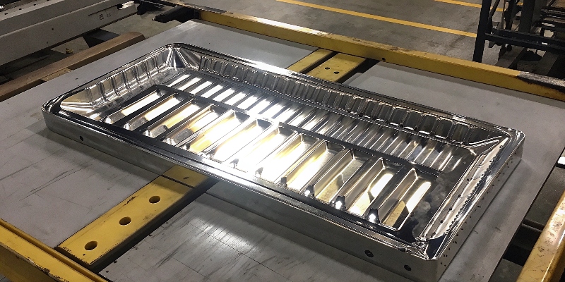
7 Trimming, Deburring & Surface Cleaning
The runner and gates are removed by trimming (press trim or cutting), and the casting is deburred to remove sharp edges and flash. Depending on the finish requirement, parts may be shot-blasted or vibratory finished to clean the surface and improve coating adhesion. This is also where cosmetic standards are enforced for visible housings.
8 Machining of Critical Features (Where Sealing & Assembly Are Won)
Even though HPDC can produce near-net shapes, LED work light housings usually require machining on critical references, such as:
– Gasket lands (flat sealing faces) for repeatable compression
– O-ring / gasket grooves to precise depth and width
– Mounting faces and locating datums for consistent assembly
– Boss holes, threads, and insert seats (for brackets, studs, or fasteners)
Machining ensures the housing remains a reliable sealing reference and keeps optical alignment stable during long-term vibration.
9 Porosity Management (Optional but Common for Waterproof Products)
Because die casting can trap tiny gas pockets, some waterproof-grade housings use additional controls such as improved venting/vacuum casting, process optimization, and in some cases impregnation (sealing micro-porosity with resin) when extremely strict leak performance is required. The need depends on design, process stability, and the target IP rating.
10 Finishing: Powder Coating / Painting (and Why)
After cleaning and pretreatment, housings are commonly powder coated for durability against corrosion, stone impact, and outdoor exposure. Typical steps include surface pretreatment, powder application, and oven curing. (Anodizing is more common for extrusions; die-cast housings often favor powder coating because it is robust and cost-effective for complex surfaces.)
11 Assembly: From Housing to Finished Work Light
With the housing ready, final assembly typically includes installing the MCPCB/LED module with a thermal interface layer, fastening the driver/electronics, routing and sealing the cable, placing the gasket, and assembling the lens/optic and bezel. Fastener torque control and gasket compression control are key to stable sealing over time.
12 Quality Control & Validation
Quality checks often include dimensional inspection (critical datums, flatness, groove dimensions), visual inspection, coating thickness/adhesion, thread verification, and most importantly leak testing (air decay or pressure tests) for waterproof models. Many manufacturers also validate thermal performance, vibration durability, and salt-spray resistance to ensure the housing system meets real duty-cycle requirements.
In short: HPDC is not just a "pour and pop out" process. For LED work lights, the real reliability comes from combining controlled melt quality, stable die temperature and shot parameters, well-designed venting, correct trimming/cleaning, precise machining of sealing references, durable finishing, and disciplined assembly and leak validation.
(2) Extrusion + machining: mainstream for light-bar bodies.
(3) Sheet-metal stamping + welding: still used in some legacy or cost-driven designs, but less competitive for high-power LED housings that need integrated heatsink geometry.
7) Why ADC12 is widely used - and why die casting is the natural match
ADC12 is widely used because its material behavior fits what LED housings need:
(1) Strong castability, enabling stable production of complex thin-wall features (fins + ribs + sealing grooves + bosses).
(2) Practical strength for vibration environments.
(3) A good match for the LED logic that the housing must act like a heatsink, moving heat toward fins and ambient air.
(4) Why die casting: it consolidates complex geometry into one part, reduces assembly and leak risk, and maintains consistency at scale. ADC12 is fundamentally a die-casting alloy family, so material and process are highly aligned.
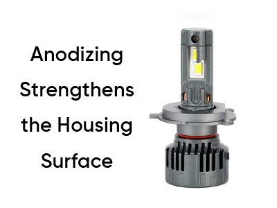
8) Why finishing systems often include powder coating or anodizing
Powder coating is common on die-cast housings because it forms a durable barrier for outdoor corrosion and impact exposure. Anodizing forms an oxide layer integrated with the aluminum substrate, improving corrosion and wear resistance, and is common on extruded profiles or products where a premium metallic appearance is desired.
Ultimately
The evolution of aux light housings is driven by heat management and long-term reliability. In the halogen era, stamped steel housings were often enough because the housing mainly served as a container and mount. In the LED era, the housing must function as a thermal platform and sealing reference, which favors aluminum alloys and manufacturing routes such as die casting and extrusion. ADC12 stands out as a widely used die-casting aluminum grade because it supports complex thin-wall geometry at scale, enables integrated heatsink features (fins, ribs, bosses, and gasket lands), and provides practical strength for vibration-heavy environments.


 2026-06-12