Your location: Home > NEWS > INDUSTRY NEWS


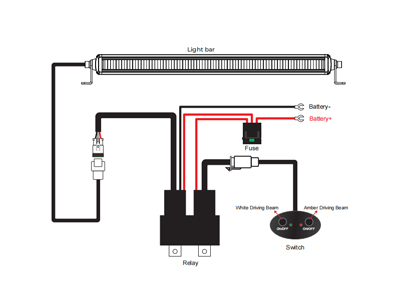
When adding aux lights, roof lights, rear work lights, air compressors, radios, and other accessories, reliability depends more on wiring than on the device. Common complaints include dim output, flicker, hot switches, blown fuses, and circuits that “look correct” but do not work. A solid setup follows four fundamentals: fuse the wiring, keep high current runs short, switch the relay coil instead of the load, and use proper grounds.
Use one independent circuit for each function you want to control separately. If two lights always turn on and off together, treat them as one circuit and share one relay.
If roof lights, rear lights, and a compressor need independent control, build separate circuits.
A 4-pin relay has two sides. Load side (high current) uses pins 30 and 87, while control side (low current) uses pins 85 and 86. Pin 30 is the power in, and pin 87 is the power out. Pins 85/86 represent the control signal input ports, which are typically used to activate or deactivate the relay. When the relay is activated, pin 87 connects to pin 30, completing the circuit.
The goal is to keep high current in the engine bay with short runs, and let the cabin switch handle only coil current.
Load side (high current path)
Control side (low current path, recommended switch-to-ground)
Switch-to-ground keeps heavy current out of the cabin and improves safety and reliability.
Yes. Two levels of protection are recommended.
A main fuse protects the main feed cable from the battery to the fuse block, while branch fuses can protect each circuit’s wiring and device. And if the circuit is properly fused at the block, an extra inline fuse near the device is usually unnecessary unless the manufacturer requires it. The fuse should protect the wire first.
Estimate current: I ≈ Watts / 13.5V
A common approach is to size the fuse at about 125–150% of expected current, while staying within the safe current capacity of the wire. Roof and rear accessories have longer runs, so voltage drop becomes more noticeable. Use thicker wire and strong grounds.
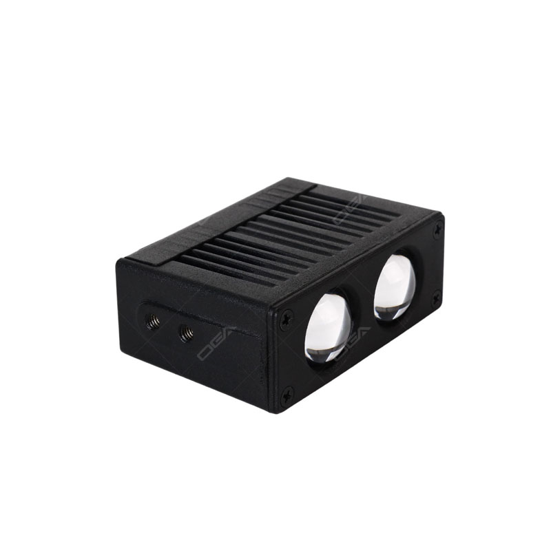
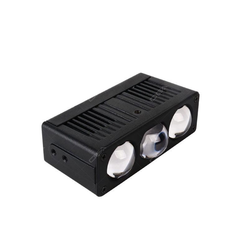
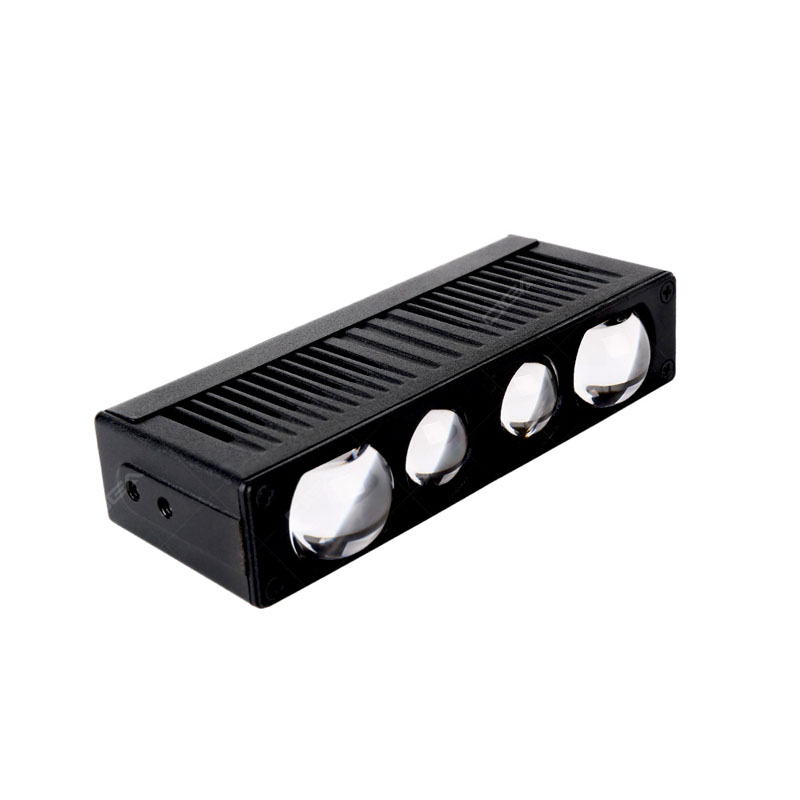
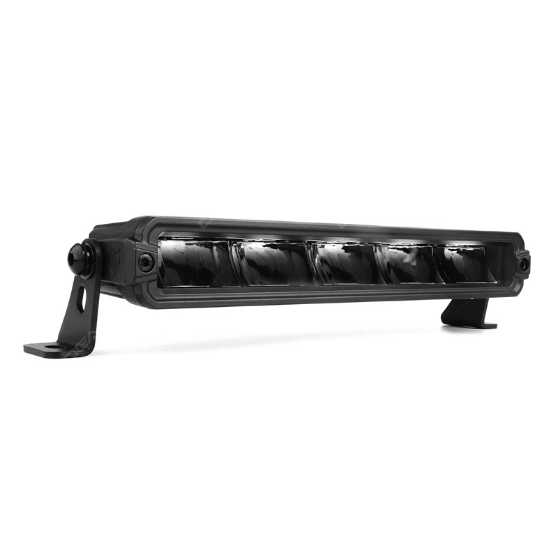
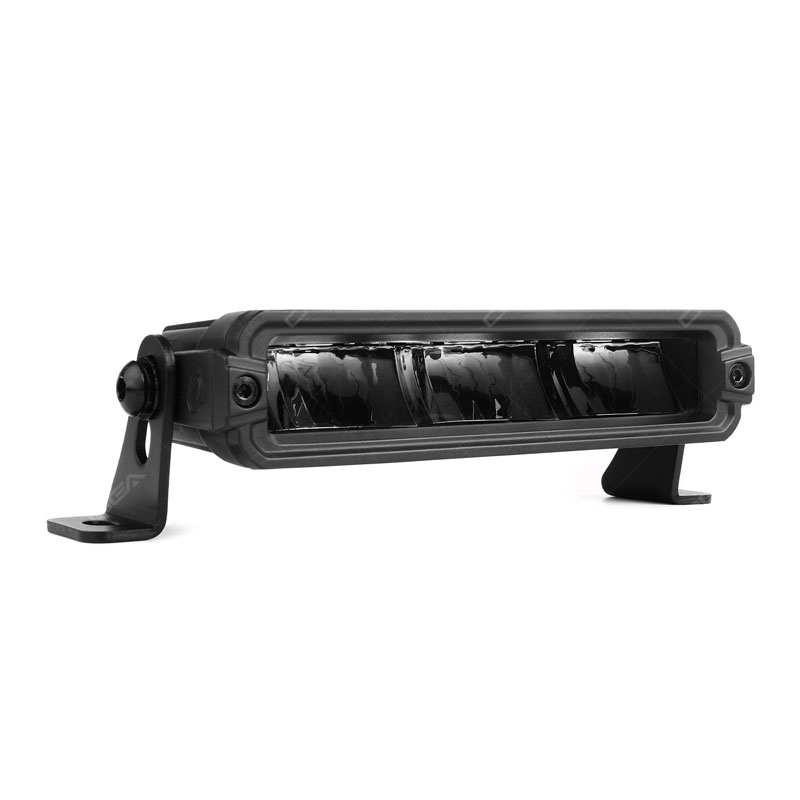
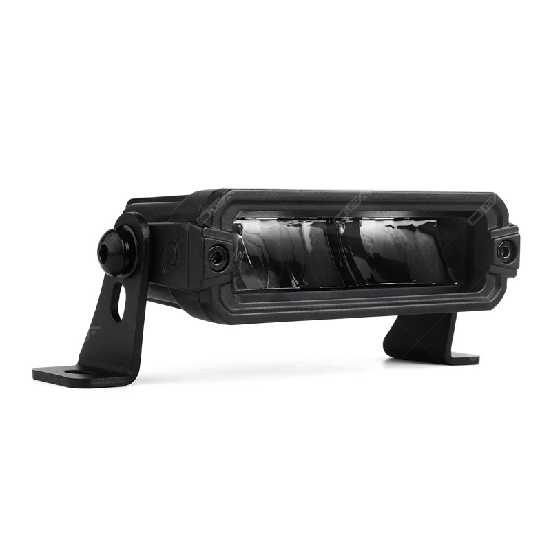
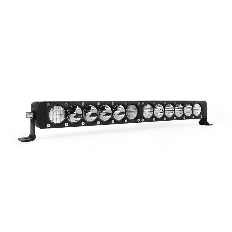
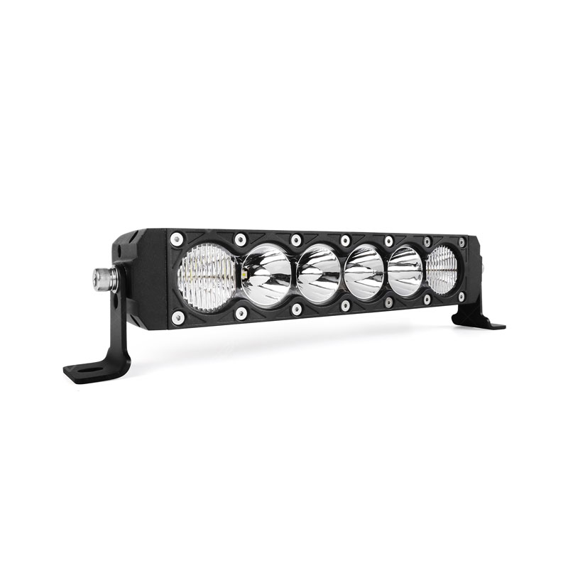
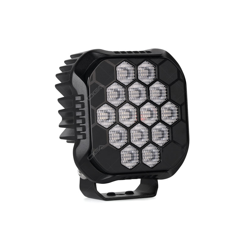
The GT15 is our company's latest modular light bar, let's use this product as an example to illustrate.

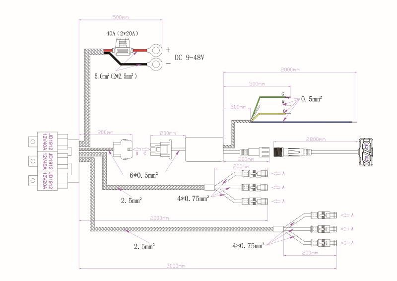
The GT15 Series Wiring System uses three relays, each controlling a different device:
The GT15 Series Wiring System uses one main fuse (40A) to protect the entire system’s electrical circuits. By merging the six light wires into two lines (main light and auxiliary light), the system simplifies wiring and ensures independent control of each device while making installation easier.
The GT15 Series uses different wire gauges: There are 6 x 0.5mm² wires for low-current signal transmission, such as switch control signals and 2 x 2.5mm² wires merge the main and auxiliary light currents, ensuring stable power supply for high-power devices. By merging six light wires into two, the wiring complexity is reduced during installation, while maintaining current stability.
Whether you use classic relays or modern switch panels, the fundamentals are the same: fuse the wiring, switch the relay coil, ground properly, and size the wire for the job. Done correctly, most accessory wiring problems disappear.
Learn more about OGA LED off-road lighting solutions and installation tips at: www.ogaled.com

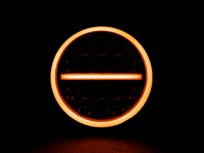
TO BE SEEN ONE SECOND AHEAD


 2026-06-12